YAMAWA-ZELX Series | JSR GROUP
May 18, 2026


YAMAWA High Performance Taps for Aerospace Industry
The demands for tapping into heat resistant alloys and stainless steels are increasing rapidly in the Aerospace Industry.
The most common heat resistant alloys are Nickel base alloys, such as A286, Inconel, Hastelloy, Waspalloy, and Titanium alloys.
There are considerable difficulties in tapping these materials due to their material features which can easily cause severe damage to taps.
YAMAWA has the best line of taps for such severe tapping conditions.
Aerospace Taps Series
YAMAWA has assorted “ZELX series” taps for threading stainless steel, titanium alloys and nickel-based alloys that are used in many aircraft parts.
For through hole
ZELX SS
Spiral Pointed Taps for Stainless Steels
 |
Suitable work materials |
|
| 303 STAINLESS STEEL | ||
| 304 STAINLESS STEEL | ||
| 410 STAINLESS STEEL | ||
| 8740 (SNCM240) | ||
| Size Ranges | ||
|
||
ZELX NI
Spiral Pointed Taps for Nickel Base Alloys
 |
Suitable work materials |
|
|
INCONEL 718, 750 |
||
| Waspaloy | ||
| Hastelloy | ||
| A286 | ||
| Size Ranges | 15-5PH | |
|
17-4PH (SUS630) |
|
ZELX TI
Left Hand Spiral Fluted Taps for Titanium Alloys
 |
Suitable work materials |
|
| Titanium alloys (Ti-6Al-4V) | ||
| Size Ranges | ||
|
||
For blind hole
ZELX SS
Spiral Pointed Taps for Stainless Steels
 |
Suitable work materials |
|
| 303 STAINLESS STEEL | ||
| 304 STAINLESS STEEL | ||
| 410 STAINLESS STEEL | ||
| 8740 (SNCM240) | ||
| Size Ranges | ||
|
||
ZELX NI
Spiral Pointed Taps for Nickel Base Alloys
 |
Suitable work materials |
|
|
INCONEL 718, 750 |
||
| Waspaloy | ||
| Hastelloy | ||
| A286 | ||
| Size Ranges | 15-5PH | |
|
17-4PH (SUS630) |
|
|
316 STAINLESS STEEL |
||
ZELX TI
Left Hand Spiral Fluted Taps for Titanium Alloys
 |
Suitable work materials |
|
| Titanium alloys (Ti-6Al-4V) | ||
| Size Ranges | ||
|
||
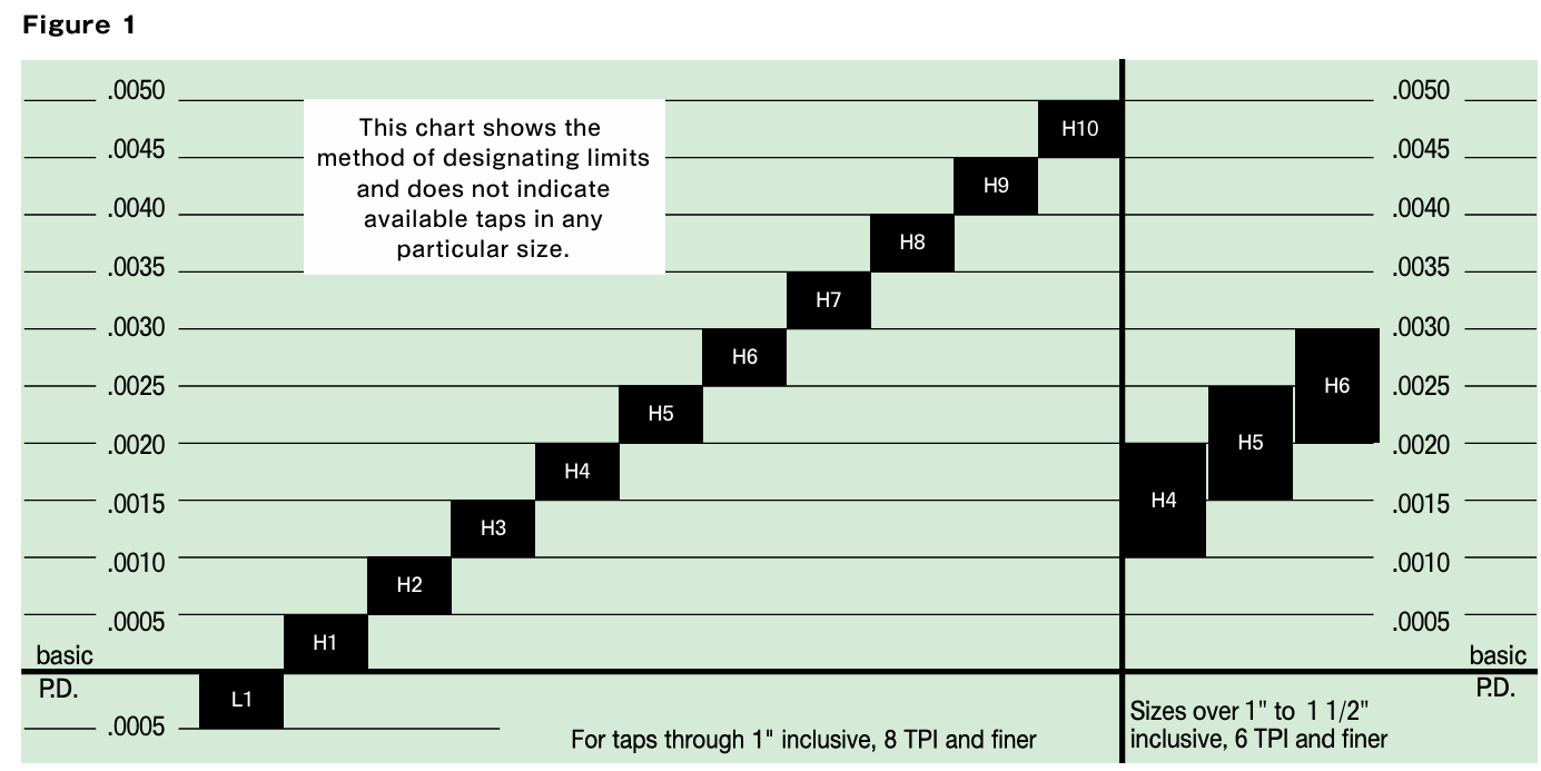
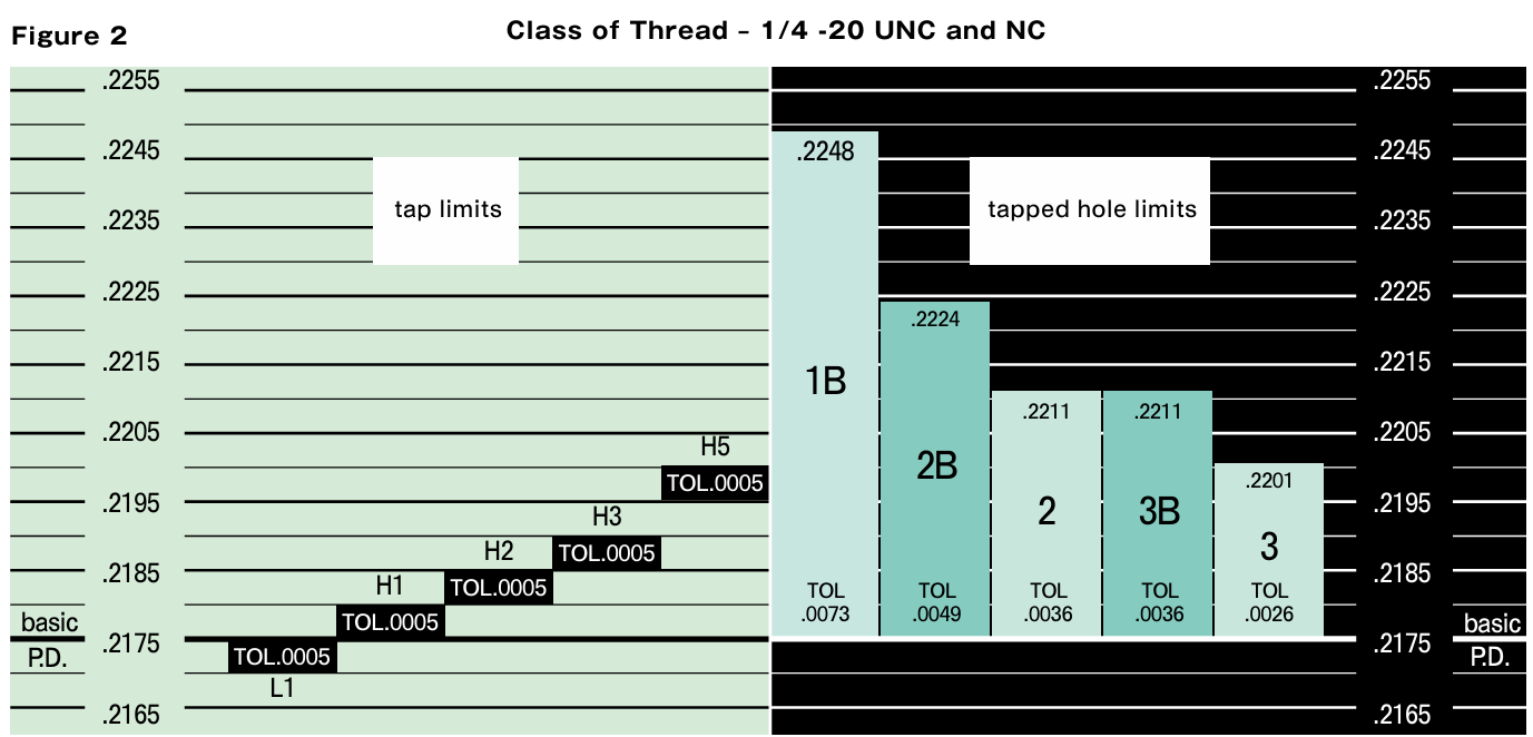
Ground Thread Tap Limits
| In addition to the nominal size and pitch of a tap, there is another important dimensional factor to be considered in selecting a ground thread tap for a given job. This factor is the “H” and “L” pitch diameter tap limits. “H” represents (high) above basic pitch diameter; “L” (low) is below basic pitch diameter. Tap limits have been established to provide a choice in the selection of the tap size best suited to produce the class of thread desired. | Figure 1 illustrates the numbering system and the .0005” diameter increment separation between successive limits. Since the starting point is basic pitch diameter, dividing the limit number by two establishes in thousandths of an inch, the amount the maximum tap pitch diameter is above basic in the “H” series and the amount the minimum tap pitch diameter is under basic in the “L” series. |
| Figure 2 illustrates the positioning of the tap limits in relation to the various classes of threads for a 1/4-20 size. |

Share on Facebook

Share on X

Share on Pinterest
Comment(s)
Recent Posts